Crossovers
A Guide to Crossovers, Controllers and Loudspeaker Management Units in PA Systems
A crossover is part of almost all live music sound reinforcement systems. Most mid-priced full-range loudspeaker cabinets have a passive crossover built into them (and some amplifiers, including our own d&b audiotechnik D12s, also incorporate crossover functions). Ultra-budget loudspeakers (the type that use piezo high-frequency horns) don't need them, and top-of-the-range touring cabinets often rely on active crossovers instead. However, the chances are - whatever system you use - a crossover of some kind will be part of it.
What it is
Crossovers come in two main flavours: Active and Passive. Passive crossovers are usually built into speaker cabinets (typically in the form of a printed circuit board with one or more capacitors and/or resistors and/or inductors mounted on it). Active crossovers usually come in the form of a 19″ 1U rack-mounted box with knobs or buttons and some sort of menu display on the front. Some - usually with system-specific EQ settings, delay and limiting functions - are described as controllers. The paragraphs below describe active crossovers.
What it does
A crossover divides a single signal into two or more frequency bands. Some are single channel (mono), some stereo, while some have flexible mono/stereo functions (for example, a crossover with two inputs and four outputs may allow stereo two-way or mono four-way operation). They are generally described according to the number of frequency bands available (two-way, three-way and four-way). A graphic illustration of the outputs of a three-way crossover is shown below. Most active crossovers allow adjustment of the crossover points, as well as independent control of the output level of each frequency band.
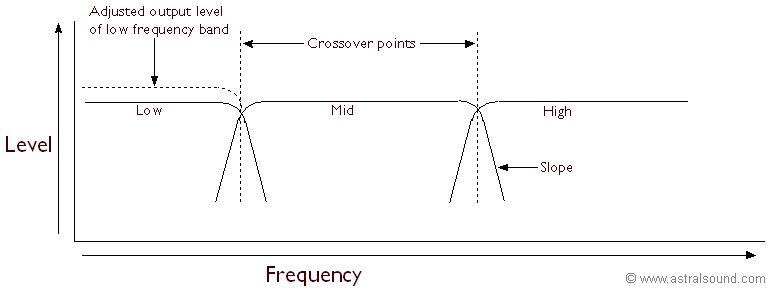
The purpose is to limit the range of frequencies any given loudspeaker driver is required to handle. This has four main advantages:
- Efficiency. Any single driver is not equally efficient at all frequencies: the output of a 10″ driver is less efficient at very low and very high frequencies; the usable range of an 18″ driver seldom extends much above 2-3kHz. Also, some cabinet designs limit the frequency response still further. The bandpass enclosure (often used to get reasonable low-frequency output from a compact cabinet) can have a usable range of less than a couple of octaves. Using a crossover to limit each range enables drivers to be used at their optimum efficiency.
- Pattern Control. Where the diameter of the driver cone in a front-loaded cabinet is equal to or less than half the wavelength of any frequency it reproduces (d ≤ λ/2), the sound tends to radiate from it non-directionally. Radiation narrows at shorter wavelengths (i.e. at higher frequencies), reaching 90° at the point where the wavelength is equal to the driver diameter (d = λ). As the wavelength becomes shorter than the driver diameter (d > λ) the radiation narrows further. Using a single driver to handle the full audio frequency range will accentuate higher frequencies directly in front of the speaker, and lower frequencies in off-axis positions. The result is very uneven frequency response across the listening area. Restricting the bandwidth of a driver limits the range of wavelengths it is required to handle, and so reduces this effect. Where horn-loaded enclosures are used together with a crossover, the resulting pattern control means that frequencies are more evenly distributed in the listening area, so that the sound in all audience positions is tonally similar.
- Increased headroom. In electronic circuits, individual frequencies add together to create a single complex waveform. The peak-to-peak voltage of the complex waveform is greater than the peak-to-peak voltage of any subset of frequencies. The maximum unclipped signal an amplifier can reproduce is limited by the voltage supplying its output stage (the peak-to-peak output voltage cannot exceed the power-rail voltage). Separating the signal into smaller frequency ranges means that the peak-to-peak voltage of each range is smaller, and places less demand on an amplifier. Typically, a two-way active crossover will allow two 200W amplifiers to achieve the same undistorted output as an 800W amplifier driving a speaker system using only passive crossovers*.
*Power is proportional to the square of the voltage (P = V2/R, where P is the power in Watts, V is the voltage in Volts, and R is the Resistance in Ohms). An 80 Volt signal into an 8 Ohm load produces 800 Watts (802 = 6,400; 6,400/8 = 800). If the signal is divided by a crossover into two 40 Volt signals, each half of the signal produces only 200 Watts (402 = 1,600; 1,600/8 = 200), so the total power produced is 400 Watts (2 x 200 Watts). The total power requirement is halved!
This degree of improvement in a two-way system is the most that can be obtained, and relies on equal division of power on either side of the crossover point. The frequency at which this occurs varies with different types of programme material, but lower-frequency sounds always require more power, so equal division of power always falls at the lower end of the audible frequency range (usually below 200 Hz, and often below 100 Hz). Also, some very low frequency sounds (80 Hz and below) require a disproportionate amount of power, so that it isn't practical to aim for a 50:50 division. In practice, most systems allow for this by using more powerful amplifiers and speakers to cover the lower frequency ranges.
- Driver protection. In any system, low-frequency signals - because they are larger - can cause an amplifier to clip. In an active system, the clipped output (containing higher frequency harmonics) powers a low-frequency driver, which typically will be able to absorb the extra power without complaining, and - because it can't reproduce the frequencies of the harmonics - without obvious distortion. In a passive system, the clipped output will be passed to the speaker's passive crossover, which will feed all the higher-frequency harmonics to the HF driver. At best this will be audible (and will sound worse). At worst, fried HF driver! Most controllers also have individually programmable limiters on each output band, so drivers are protected from inexperienced users.
How it works
It uses bandwidth limiting filters - each of which has a steep cut-off below and/or above its range (24dB/octave is typical) - to separate the input signal into multiple outputs. In some, the cut-off slope (and in some of those, even the type of filter: Bessel/Butterworth/Linkwitz-Riley, etc.) is user-determined.
Controls that can be included (often on a menu, sometimes on knobs) are:
Input Level (or Input Gain)
Some crossovers allow the user to increase or reduce the input signal. This will otherwise be determined by the preceding device in the signal chain (usually the mixer, or equalisers if they are in-line). Some also allow switching between −10dBV and +4dBu operation.
Crossover type
Many crossovers can be used in a variety of ways (e.g. as 2-way or 3-way stereo, or 4-way mono).
Summed Mono
Some crossovers allow the sub-bass frequencies from left and right channels to be added together and provide a single output. Low frequencies are less directional, and low frequency instruments (e.g. bass guitar, kick drum) will be panned centrally in a stereo mix anyway, so this arrangement is useful.
Frequency
The high and low cut-off points can usually be configured for each band.
High Pass
Sometimes a cut-off point is available for the lowest frequency band (to protect against subsonic or DC signal).
Low Pass
Sometimes a cut-off point is available for the highest frequency band (to protect against inaudible high frequencies which - although inaudible - can still damage HF drivers).
Filter type
The type of filter, typically Bessel, Butterworth or Linkwitz-Riley (consult loudspeaker literature for which is suitable or recommended) is sometimes selectable. Linkwitz-Riley is the most common, and is probably the best default if you have no other information to go on.
Filter slope
Typically ranging from 6dB/Octave to 24dB/Octave or higher. Sometimes this may be given as a Q value. Less than 12dB/Octave may not be enough to protect high-frequency drivers from low-frequency signals.
Gain/Gain Adjustment
The gain of each output band may be adjustable, typically within a limited range (up to about +/−6dB), but sometimes from −∞ (mute) to +20 dB or more.
Amplifier Sensitivity
Some crossovers allow adjustment to cater for amplifiers with different input sensitivities.
Amplifier Gain
Some crossovers allow adjustment to compensate for using amplifiers with different gains on different frequency bands.
Limiter/Compressor
Some crossovers (and most controllers) allow the user to set limiters to prevent output signals exceeding amplifier or speaker capacity. Setting limiters can be quite complicated, as it relies on exact knowledge of amplifier sensitivity and gain, coupled with knowledge of speaker ratings. Using compression enables more gradual gain reduction as the output signal approaches safe limits, making the effect of limiters less audible.
EQ
Many crossovers allow the user to tailor the overall EQ (usually to match known loudspeaker configurations), and some - particularly multi-system controllers/loudspeaker management systems - have comprehensive EQ facilities, allowing multi-band parametric equalisation of each individual output.
Delay
Where some speakers in an array are mounted further back or further forward than others (whether in the same or separate cabinets), phase relationships can be affected, and this can cause audible (and undesirable) side-effects. The delay parameter allows phase alignment of the individual speakers. However, you may require signal-generating and measuring devices to set it up correctly.
How do you use it?
If all else fails, read the manual (for some highly-specified units the manual can be quite a read!).
Generally, you will also need to read your loudspeaker manufacturer's literature to establish recommended crossover points (as well as filter types/slopes, gain adjustments, etc.). As a rule, it is safe to use higher-frequency crossover points than those recommended (whether or not it also sounds OK), and dangerous to use lower-frequency points than those recommended. Using higher than recommended crossover points may adversely affect output pattern, as it may well mean that lower-frequency drivers will be handling frequencies with wavelengths shorter than cone or horn exit diameters (see Pattern Control", above). Using crossover points with a lower frequency than recommended usually means that HF drivers will be subjected to higher voltages than they are designed to withstand, leading to rapid failure.
Setting crossover/controller limiters correctly requires exact knowledge of power amplifier and speaker capacity. Unless it is driven to clipping, an amplifier's output voltage is determined by the input voltage and its voltage gain. The limiters should be set so that the output voltage cannot exceed the speaker's rated capacity (if the information to calculate this is not available there is no guarantee your equipment will be protected).
If your amplifiers do not have inbuilt clip limiters and you cannot set crossover limiters accurately, you should at least set them so that amplifiers cannot be driven to clipping. To do this:
- With the system set up normally, disconnect your speakers from the amplifier's outputs.
- Send a test signal to the crossover inputs. Broadband pink noise with a 6dB crest factor is an ideal signal. Otherwise, use a sine wave within the crossover band's range (e.g. 80 Hz for subs, 600 Hz for mids, 3 kHz for high-frequency amplifiers).
- Increase the test signal level until the amplifier's clip lights come on.
- Reduce the limiter threshold until the lights go out.
- If you used a sine wave test signal, either reduce the limiter threshold by another 3-6 dB, or use a dynamic signal to check that instantaneous peaks cannot exceed the limiter threshold.
If in doubt, set the threshold lower than necessary.
If the system has arrived with the crossover/controller already configured, DO NOT TOUCH IT UNLESS YOU KNOW WHAT YOU ARE DOING.
Do you need one?
If you use separate amplifiers for loudspeakers covering different frequency ranges, you almost certainly need one, unless your amplifiers incorporate some crossover functions: some amplifiers include comprehensive processing facilities, and others have at least basic high-pass and low-pass filters, which may make a dedicated crossover unneccesary.
What sort do you need?
Most loudspeaker manufacturers can supply system-specific controllers, and if you will only ever use one kind of speaker system these are in most cases trouble-free, and guaranteed to be set up correctly.
If you will be using a number of different loudspeaker systems, go for a crossover/controller that allows adjustment of all the necessary parameters. Preferably, it should also allow different combinations of settings to be saved and recalled (so that you only have to set up a given system once).